


Rotor balancing solutions
Single, Dual and Multiplane Vibration Balancing
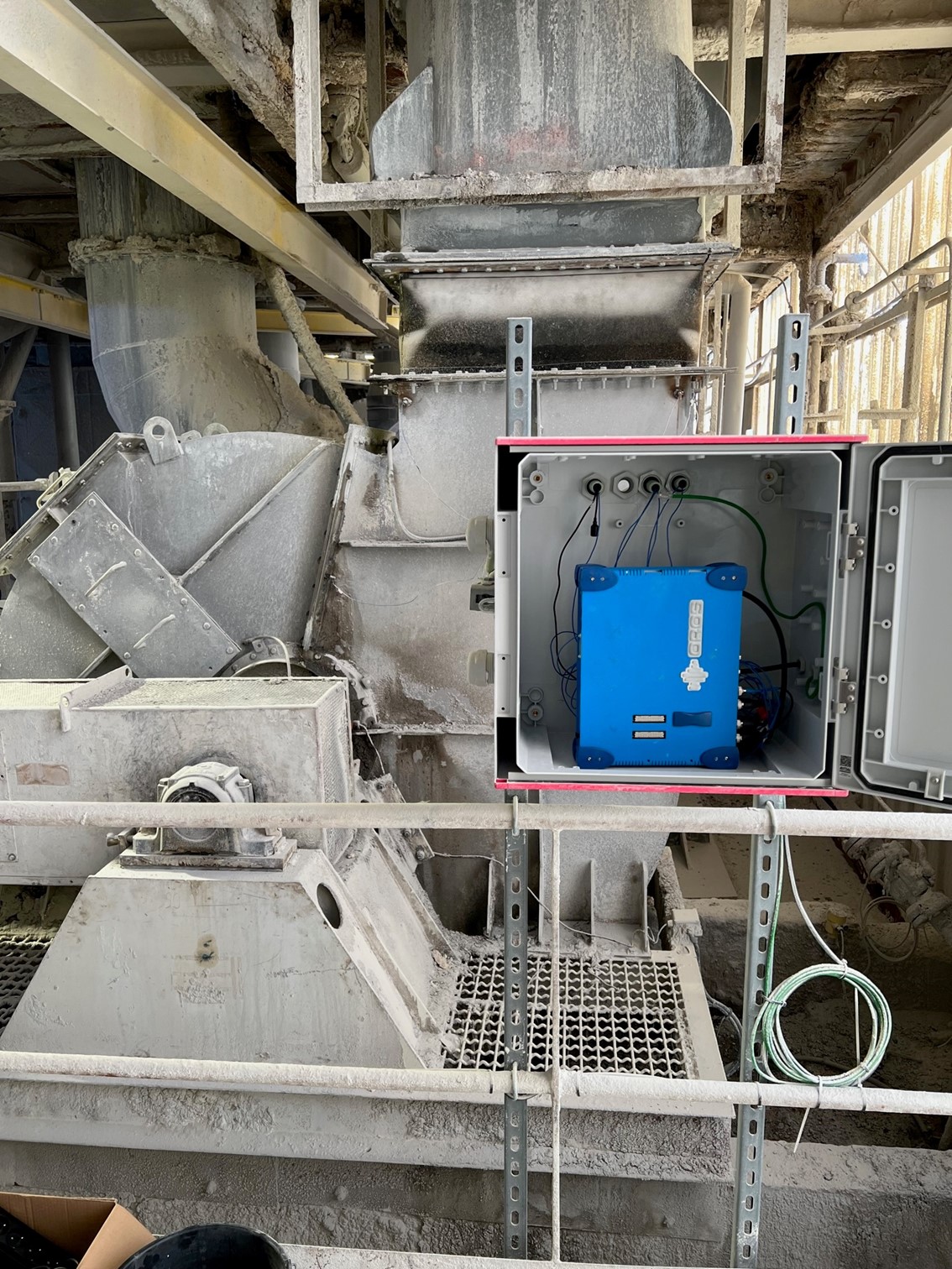
Rotor balancing solutions are software modules for balancing rigid and flexible rotors. These modules are well-suited for shop balancing or in-situ field balancing. They are designed to run on OROS analyzers.
Datasheet
First be logged into myOROS
or quickly create an account
Our catalog
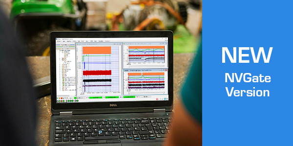
Download the latest version
First be logged into myOROS
or quickly create an account
OROS Balancing Solutions are software modules for balancing rigid and flexible rotors. These modules are well–suited for shop balancing or in–situ field balancing. They are designed to run on OROS analyzers.
2 modules are available:
Single/Dual plane software module
It is particularly suited for shop or field balancing of rotors operating in their rigid body region (well below their first critical speed).
Multiplane software module
It is designed to balance rotors above the first critical speed: meaning in the region where the rotor deforms and reaches its first bending mode.
Flexible acquisition
- Acquisition from a wide choice of hardware platforms (sizes and weights) thanks to the OROS 3–Series instruments’ range’s flexibility.
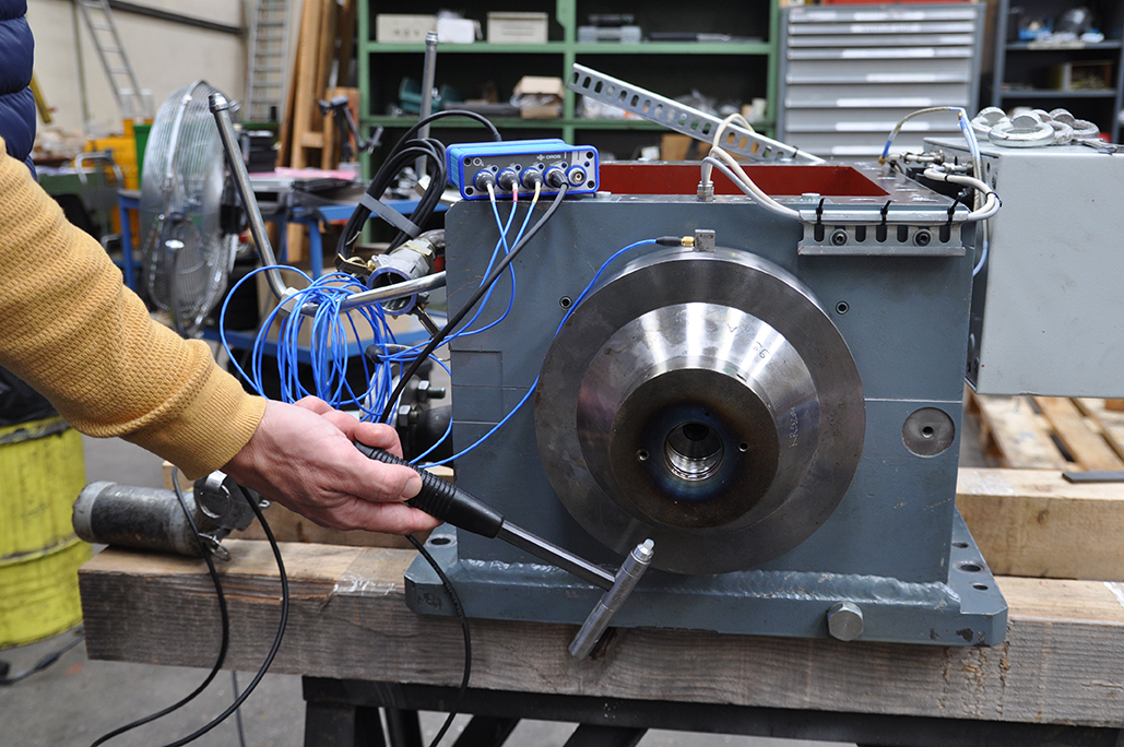
- Accepts signals from accelerometers, velocimeters or proximity probes.
- Up to 32 sensors depending on the instrument platform.
Accurate balancing
- Source data for the balancing operation (1X amplitude and phase) provided in real time by the powerful OROS Synchronous
Order Analysis plug–in analysis engine reputed for its high precision.
- Oversampled tach input at 6.4 MHz to provide the best phase
accuracy.
- High quality digital signal provided by the state of the art
electronics of the OROS instruments.
Designed for efficiency
- Correction planes and measurement planes managed independently and flexibly,
- Flexible weight map configuration with correction mass split or by step of 1°,
- Add or remove weight by drilling,
- Keep or remove test mass,
- Prognostics of residual vibration (“what if” feature),
- Trim balancing,
- Report generation,
- Available in English, German, and French languages.
Single/Dual Plane Balancing (ORNVS-BAL-SDP)
- 1 or 2 balancing planes
- Rigid rotors
- 1 to 4 sensors (1 or 2 per bearing)
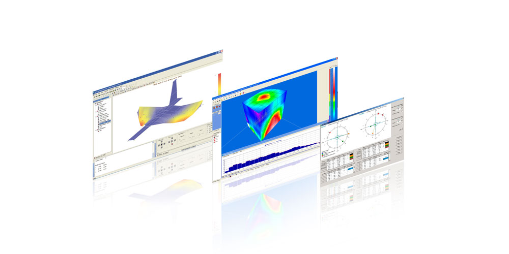
- Real time acquisition and 1X polar diagram (amplitude and phase).
- Steady state speed acquisition
- Acceptance of residual unbalance according to ISO 1940 / Balancing quality selection
- Size and weight: optimum size with O4. Runs on the OROS instruments’ platform
- Trim Balancing
- Report generation
- Designed for non–experts
Easy to set-up, fast to learn
Being guided by the wizard, the user can perform a balancing operation in a few clicks and without any special knowledge about balancing theory: Training time is
reduced.
It is designed for shop or field balancing. Steps to the balancing report are optimized and guided. Testing and
correction time are minimized. Thanks to the dedicated interface, the risk for errors is limited.
Practical and applied tools for user ease and efficiency
Based on the acceptance circle the residual unbalance is compared to the acceptable level required by ISO
1940 (based on rotor weight, balancing quality grade and operating speed should be provided).
Using the unique prognostics feature, and providing the actual correction mass implemented, the residual unbalance can be easily estimated and compared to the
acceptable level.
The history of one rotor can be saved in the project and trim balancing allows further balancing with no requirement for carrying additional trial tests.
The report feature lets the user print a balancing report and keep track of the modifications made.
Multiplane Balancing (ORNVS-BAL-MP)
- 1 to 14 planes
- Flexible or rigid rotors
- Up to 32 channels for 1X acquisition
- Import 1X data (Amplitude and Phase vs. RPM from ORBIGate or from manual input from text files (csv template)).
- Run–up, Coast–down, steady–state
- Balance at multiple speeds or ranges of speeds
- Calculate predicted Amplitude vs. RPM after balancing correction
- Multiplane report generation
A simple solution for a complex problem
Multiplane balancing is a delicate operation that requires a high level of expertise from the user. The rotor is operated above its first critical speed and will be deformed. The purpose of OROS’ multiplane balancing module is to bring a simple and dedicated tool to the fingertips of the user to solve this complex problem.
Transient 1X data acquisition
Based on the OROS multichannel instruments the 1X data are collected real–time during transients (run–up, coast–down) or steady–state phase at the different steps of the balancing operation (initial, trial, trim). At that stage, the data are displayed as Bode or Polar diagrams. Data can also be entered via other collecting sources including manual input.
Correction weights calculation
The data are then processed offline in the software after selection of the speeds for which unbalance should be reduced.
Residual unbalance prognostics
The residual unbalance after implementation of the correction masses can be calculated for the different speeds of the transient.
Balancing applied training
Basic Principles and Procedures, Practical Case on Training Kit
- Objective
Unbalance is the most common issue on a rotating system.
From high speed small rotating system to heavy industries machinery, balancing a rotor system is a sensible task. OROS leads you to understand the method and principle for balancing: from the theory to a practical test.
- Program
> Balancing phenomena, cause and possible damage
> Order analysis, how to setup an analysis for balancing
> Rigid or dynamic balancing?
> Our solution, a dedicated and easy to use interface
> Number of planes and measurement points
> How to start a good procedure?
> Sequence for balancing, test run, correction and trim balancing
- Who Should Attend?
Technician or engineer who wants to get theoretical and practical basis for balancing
- Duration 0.5 day
Contact Customer Care to know more.
Balancing a rigid rotor - how to balance a rigid rotor in less than 5 minutes!
Flexible Rotor Balancing - Application to turbochargers
Turbocharger rotors are small items, but, because of their high rotational speed, they may experience several critical speeds and should be considered as flexible. For this reason it is not possible to balance the rotor at only one speed. Several speeds should be considered, including a run-up and a run-down speed.
The number of possible balancing planes is typically up to 4: 2 on the compressor side and 2 on the turbine side. Depending on the case and the material characteristics (drilling, scraping, grinding) on each of the planes, it may not be possible to add or remove weight. A selection of planes must hence be considered: typically the plate on the compressor side may be a good choice. In principle, the blades stay untouched.
The balancing procedure should be considered in a similar manner to a modal analysis. The idea is to determine the relationship between the response (vibration measured at the bearing) and the exciting force (the imbalance). Therefore, adding a known weight is like striking a structure with an impact hammer and measuring the injected force. Once the relationship is known (the influence coefficient matrix), it is easy to locate the original force (imbalance) and propose a correction weight.
The idea is to excite the 1X component with an imbalance force. The excited response should be due to the imbalance as much as possible. Any other reason (typically, a structural resonance from the bearing) will introduce errors, reduce precision, and make the balancing correction less efficient.
Best practices for flexible balancing
The different choices that the user has to make concern, in chronological order:
- Sensor positioning: Sensors should give results that are highly impacted by the imbalance (original or trial weight-related). Typically, accelerometers are used: they should preferably be positioned in a direction in which the bearing is less stiff (often the horizontal direction).
- Input range setting: After the initial balancing, the 1X component may appear to become It may be necessary to adapt the input range (doing an auto range, for example).
- Positioning of trial weights: The positions of the trial weights are also important, as they are required to provide new information compared to the original run or other trials.
- RPM run-up/down rate: It is important to have the same rotor acceleration for the initial runs and the trial runs. The structure may not behave in the same way, depending on how quickly the speed increases or decreases.
- Data: Data on the different runs should be synchronized from one to another. To calculate the influence coefficient matrix, the data on the different runs (Initial, Test 1, Test 2,) should be comparable at the exact same RPM value.
- RPM selection: this is probably the most sensitive point to take into account when achieving balancing. The data should be selected with care because the wrong data or too much data would lead to biased results.
- Trim balancing, or not: To be able to carry out trim balancing (further balancing after implementing the rotor weight correction), it is important to be sure that the system stays linear; in other words, that the same influence coefficient matrix can be used. If it cannot, this measurement must be used as a new initial run.
Hopefully these are some useful criteria that will help users make the right choices!
All our software solutions are customizable to be integrated in your environment. Please contact our the OROS Customer Care Department and visit the customization services webpage.